Creating a custom motion vector blur using trackers.
The original version of this article can be viewed here
As a compositor, one of our daily tasks is to integrate plates of elements (dust, smoke, fire, water etc.) into our shots. Rarely do we get plates that were filmed specifically for the exact shot we are working on, so we rely on libraries of pre-filmed (stock) elements.
The problem
No matter how extensive the stock library, these plates will almost always have to be manipulated in some way (re-timed, scaled etc.) to fit in with the specific shot. Elements that are fast and contain lots of small details (water splashes, dust bursts, explosions etc.) are typically filmed at high frame-rates so we capture maximum detail and have more options in how to retime the shot. However, this usually also gives us an unnaturally sharp image due to the fast shutter time, so we often have to artificially add motion blur to match the plate into which we are compositing.
Adding motion blur to elements
Nuke has several ways of adding motion blur to an image. Let’s quickly look over a few and explain what their specific problems are.
Frame Blending
A cheap way of roughly simulating motion blur is to use a FrameBlend. This can be useful to help smooth a re-timed plate, but if the footage is fast moving it will leave “ghosting” artifacts making small particles look like dotted lines.
Optical Flow
Another option is using nodes such as OFlow, Kronos or RealSmart MotionBlur, all both use the same underlying technology – optical flow. This is a process of analyzing the pixels in an image sequence, and calculating their relative movement frame by frame. The resulting motion vectors can be used to recreate missing frames when retiming footage, or generate motion blur that is applied only to the specific moving areas of an image.
Optical flow works in a similar way to a 2D tracker – it looks for a recognizable pattern in the pixels and tries to find the same pattern on the next frame. Only optical flow does this across the whole image to track all motion within the frame. As long as there are large trackable features with consistent textures in our footage, OFlow can do a pretty good job of calculating movement. But if the image changes a lot frame by frame then you can often end up with artifacts where it fails to calculate the track.
One thing that optical flow really struggles with is footage of small particles. Whilst the human eye can do a very good job of analyzing overall motion in footage, if the features are all very similar in appearance (water droplets in a splash, dirt particles in an explosion) then OFlow has no idea which particle is which when it examines the next frame.
Vector Blur
If our footage was rendered by a 3D program, there is usually the option of additionally rendering a motion vector pass. A motion vector pass (also called a velocity pass) is a rendered image that represents the speed at which each pixel is moving. The red, green and blue channels contain values that don’t represent visible color, but instead the velocity (in x, y and z).
When rendering an image from a 3D program, it is often useful to render it without motion blur, and to add the motion blur later in our compositing package with the use of the motion vector pass and the VectorBlur node.
As we are not working with rendered 3D images in this case, we don’t get to render a handy motion vector pass. So I thought I would figure out a way that we could artificially create one – more on that in a moment.
MotionBlur2D
The MotionBlur2D node will take data from a Transform node and generate a motion vector pass based on this information, which can then drive a VectorBlur. The limitation of this is that the motion vector data has a single value across the entire image, so the blur is the same amount everywhere. This is fine for matching motion blur generated by a camera move, but not if different elements within the shot are moving in different directions. However, it gives me a starting point for building a tool for the job.
The solution
So let’s get stuck in to an actual shot and use this stock water splash element. We will ignore retiming it for now and assume we just need to increase the motion blur to match another plate.
The droplets all move in different directions, but generally follow the same parabolic arches in localized areas.
The broad idea was to use the same method that Motionblur2D uses – to take transform data and calculate motion vectors from it. The trick would be to restrict this to specific areas rather than the whole image, then combine a number of different Transforms that represent different parts of the image.
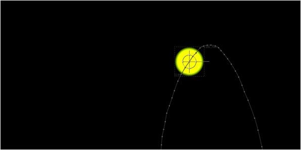
First of all I created several Transform nodes and hand tracked some of the larger water droplets. The droplets change shape throughout the shot and sometimes vanish for a few frames, but as long as I keep the Transform generally following their motion it will be sufficient.
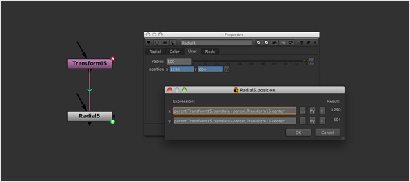
Now to create a color based on the velocity. I choose one of the Transform nodes and create a corresponding Radial node. First thing is to create a custom 2D Position Knob in the Radial called “position” and expression link it to the Transform node.
I’ve used the Transform node’s “center” plus its “translate” values to give me an absolute (rather than relative) position on the screen.
parent.Transform15.translate+parent.Transform15.center
I add another custom knob here called “radius”, which I set to 100px as default, then expression link the “area” values of the Radial to draw a circle centered around the “position” value, and of value “radius” in width.
Next I add another custom knob called “velocity” and expression link it’s value to “position”.
For this I look at the “position” value on the current frame (“t”), and subtract the value from the frame before (“t-1″). This gives me the number of pixels the Transform has moved in one frame, or in other words its velocity.
position(t)-position(t-1)
Finally I expression link the “red” and “green” values of the Radial’s “color” to the velocity.
This gives us roughly what we need – a localized motion vector pass for a specific droplet.
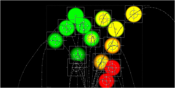
I now need to repeat this process for the other Transform tracks. I duplicate the Radial and expression link each new node to a corresponding Transform. I then add all of the outputs together with a Merge.
If we look at the result you will see a rudimentary velocity pass, where the values correspond to the motion at each tracked point. You will notice that some of areas of the velocity output have negative values where the droplets are moving right to left, or downwards.
But how to fill in the gaps? Surely we don’t have to do this for every droplet in the entire plate?
Well, no – here is why I made sure that each Radial had an alpha value of 1, so I use the same trick as my colour smear tool.
First we apply a 300px blur across the whole image…
…and then unpremultiply the result. This spreads the values out, and averages the values into the gaps.
The Result
Let’s see if this now works. I shuffle the RGB values into the “motion” channel of of our water splash plate. I then add a Vectorblur node and tell it to use the values from the “motion” channel.
As you can see, the end result is pretty smooth.
Despite the droplets moving in different directions, we get a nice motion blur that correctly matches their velocity. I’ve dialed the blur quite high so that it is easy to see – we can increase / decrease this by adjusting the “multiply” knob on the VectorBlur node. If we compare it to the next best method (OFlow) and the results are far better as they lack artifacts.
Tidying Up
There are a few things we can now do to improve our setup.
Firstly, the velocity expression is only looking at the motion leading up to the current moment (i.e what happens between the previous frame and the current frame), so this equates to having our shutter offset set to “end” in a normal motion blur setting. I will add two more velocity calculations. One called “velocity_start” will compare the value on the current frame to the value on the next frame (equivalent to having our shutter offset set to “start”.
position(t+1)-position(t)
The second knob, labelled “velocity_centered” will look at the both the “start” and “end” velocities, and create an average between them – this will equate to having our shutter offset set to “centered”.
((position(t+1)-position(t))+(position(t)-position(t-1)))/2
Next I will wrap the Radial up in a Group called “vector_module”, and adjust the expressions to link to any Transform node that is plugged in to the Group’s input. This makes updating the vector_module easier as you don’t need to hard-code the name of the Transform node you want to link to – simply plug it in to be used.
The benefit now is that you can also plug in a Tracker node (or indeed any node that outputs a “translate” and “center” value). I also moved the “radius” value to a slider on the Group, as this is now the only value you might need to manually adjust, and added a drop-down menu to select which shutter offset to use.
Finally, I did a lot of thinking about whether using the “plus” operator to Merge all of the vector_modules together was correct. Where a lot of the trackers overlap at the start of the shot, the velocity value becomes un-naturally high do to the accumulated result of the values being added together. I did explore using a MergeExpression node to counter this, which used the following expression.
Ar>0&&Br>0?max(Ar, Br):Ar<0&&Br<0?min(Ar, Br): (Ar+Br)
So, if the values from the A and B plate are both positive, it will find the "max", if they are both negative it will find the "min" and if they are a combination (or one value is 0) then it will "plus" them instead.
However, I ran some tests after the 300px blur is applied and the difference in results was almost imperceptible. Therefore I stayed with a standard Merge as I can plug many inputs into a single node.
The Nuke Node
I've pasted code below for the "vector_module" Group - to use it, simply plug your own Transform or Tracker nodes in. As usual, I'll point out that many things could probably be improved - feel free to further modify the node and send me your result - I'll update it here with an appropriate credit.
Group {
 name vector_module
 help "For creating a custom motion vector pass based on translate data. Plug in a Transform or Tracker node that corresponds to a specific moving area of your image. Merge multiple instances of the vector_module together to create a motion vector pass.\n\nSee http://richardfrazer.com/tools-tutorials/custom-motion-vector-blur-using-trackers for a full tutorial."
 selected true
 xpos -673
 ypos 2300
 addUserKnob {20 User}
 addUserKnob {4 shutter M {centred start end ""}}
 addUserKnob {7 master_radius R 1 1000}
 master_radius 210
 addUserKnob {26 ""}
 addUserKnob {26 credit l "" +STARTLINE T "Vector Module v1.0 by Richard Frazer www.richardfrazer.com"}
}
 Input {
  inputs 0
  name transform_2d
  xpos -313
  ypos -386
 }
 Shuffle {
  red black
  green black
  blue black
  alpha black
  name Shuffle1
  xpos -313
  ypos -298
 }
set N310a8a10 [stack 0]
 Radial {
  area {{position.x-radius i} {position.y-radius i} {position.x+radius i} {position.y+radius i}}
  color {{parent.shutter==1?vector_start.x:parent.shutter==2?vector_end.x:vector_centred.x i} {parent.shutter==1?vector_start.y:parent.shutter==2?vector_end.y:vector_centred.y i} 0 1}
  name Radial1
  xpos -313
  ypos -200
  addUserKnob {20 User}
  addUserKnob {7 radius R 1 100}
  radius {{parent.master_radius i}}
  addUserKnob {12 vector_centred}
  vector_centred {{((position(t+1)-position(t))+(position(t)-position(t-1)))/2 i} {((position(t+1)-position(t))+(position(t)-position(t-1)))/2 i}}
  addUserKnob {12 vector_start}
  vector_start {{position-position(t-1) i} {position-position(t-1) i}}
  addUserKnob {12 vector_end}
  vector_end {{position(t+1)-position i} {position(t+1)-position i}}
  addUserKnob {12 position}
  position {{parent.input0.center.x+parent.input0.translate.x i} {parent.input0.center.y+parent.input0.translate.y i}}
 }
 CheckerBoard2 {
  inputs 0
  name CheckerBoard1
  xpos -148
  ypos -195
 }
 Switch {
  inputs 2
  which {{"parent.input0.name +1"}}
  name Switch3
  xpos -313
  ypos -100
 }
 Output {
  name Output1
  xpos -313
  ypos 27
 }
push $N310a8a10
 Viewer {
  input_process false
  near 0.9
  far 10000
  name Viewer1
  xpos 30
  ypos -247
 }
end_group
Acknowledgments
This technique borrows heavily from a trick for creating custom displacement maps that was shown to me by Emmanuel Pichereau at One Of Us.
All of the stock footage elements above are from the Action Essentials 2 collection by Video Copilot. If you want to have a play with the full 2K plates then this collection is great value for money.
The example of the CG render with motion vector pass is taken from this tutorial - you can also download the CG renders there to have a play yourself.
 - over 1,000 free tools for The Foundry's Nuke


Comments
RSS feed for comments to this post